Basically, it can be said that the main function of the LED driver power supply is to convert the input AC voltage source into a current source whose output voltage can vary with the LED Vf (forward conduction voltage drop). As a key component in LED lighting, the quality of the LED driver directly affect the reliability and stability of the overall lamps.
▲ The Vf variation range of LED Strip beads is not considered, resulting in low efficiency of lamps and even unstable work
The load end of LED lamps is generally composed of a number of LEDs connected in series and parallel, and its operating voltage Vo=Vf*Ns, where Ns represents the number of LEDs connected in series. The Vf of an LED varies with temperature. Generally, at a constant current, Vf becomes lower at high temperature and higher at low temperature. Therefore, the operating voltage of the LED lamp load at high temperature corresponds to VoL, and the operating voltage of the LED lamp load at low temperature corresponds to VoH. When selecting an LED Light driver, it is necessary to consider that the output voltage range of the led power supply is greater than VoL~VoH.
If the maximum output voltage of the selected LED driving power is lower than VoH, the maximum power of the LED may not reach the actual required power at low temperature. If the minimum voltage of the selected LED driver power is higher than VoL, the output of the LED power may exceed the working power at high temperature. range, the work is unstable, and the LEDs and lanterns will flicker and so on.
However, considering the comprehensive cost and efficiency, we cannot blindly pursue the ultra-wide output voltage range of the LED lighting driver: because the drive power supply efficiency is the highest when the led power supply voltage is only in a certain range. If the range is exceeded, the efficiency and power factor (PF) will deteriorate. At the same time, the output voltage range of the led power transformer is too wide, which will lead to increased costs and unoptimized efficiency.
▲ The power margin and derating requirements are not considered
In general, the nominal power of LED power driver refers to the data measured under rated environment and rated voltage. Considering that different customers will have different applications, most LED driver suppliers will provide power derating curves in their product specifications (common load vs ambient temperature derating curves and load vs input voltage derating curves).
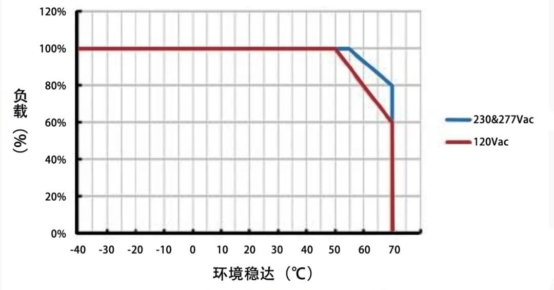
As shown in Figure 1, the red curve represents the power derating curve of the load of the LED drive power supply changing with the ambient temperature under the condition of inputting 120Vac. When the ambient temperature is lower than 50°C, the drive power is allowed to be fully loaded at 100%. When the ambient temperature is as high as 70°C, the drive power can only be derated to 60% of the load. When the ambient temperature changes between 50-70°C, the led power supplies load decreases linearly with temperature.

Figure 1 Power derating curve of load vs ambient temperature
The blue curve represents the power derating curve of the load changing with the ambient temperature when the LED power supply is input at 230Vac or 277Vac. The principle is similar.
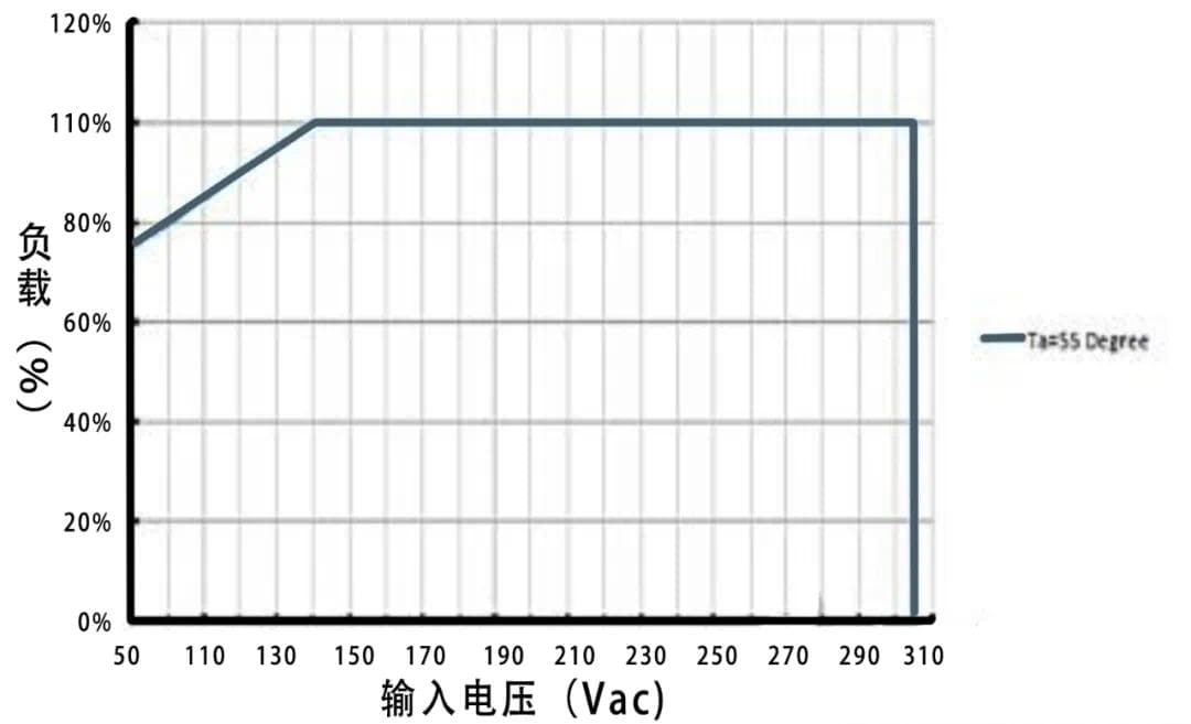
As shown in Figure 2, the blue curve represents the derating curve of the output power of the LED driver power supply as the input voltage changes when the ambient temperature is 55°C. When the input voltage is 140Vac, the load of the driving power supply is allowed to be 100% full load, and the input voltage is lowered; if the output power remains unchanged, the input current will increase, resulting in increased input loss, reduced efficiency, and increased device temperature. It may exceed the standard, and may even lead to device failure.

Figure 2 Power derating curve of load vs input voltage
Therefore, as shown in Figure 2, when the input voltage is less than 140Vac, the output load of the driving power supply is required to decrease linearly with the decrease of the input voltage. After understanding the above derating curve and corresponding requirements, when selecting LED light power supply, it should be considered and selected according to the ambient temperature and input voltage during actual use, and an appropriate derating margin should be reserved.
▲ Do not understand the working characteristics of LED
A customer once requested that the input power of the lamps be a fixed value with a fixed 5% error, and the output current can only be adjusted for each lamp to reach the specified power. Due to the different working environment temperature and different lighting time, the power of each lamp will still have a big difference.
The customer put forward such a request, although there are considerations of marketing and business factors. However, the volt-ampere characteristics of the LED determine that the power supply LED driver is a constant current source, and its output voltage changes with the LED load series voltage Vo. When the overall efficiency of the led strip light driver is basically unchanged, its input power varies with Vo.
At the same time, the overall efficiency of the led driver will increase after thermal balance, and under the same output power condition, the input power will decrease compared to the moment of starting up.
Therefore, when formulating requirements, users of led light power supplies should first understand the working characteristics of LEDs, avoid proposing indicators that do not conform to the principle of working characteristics, and at the same time avoid indicators far exceeding actual needs, so as to avoid excess quality and cost waste.
▲ Failed during the test
A customer once purchased many brands of LED drivers, but all samples failed during the test. Later, after on-site analysis, it was found that the customer used a self-dual voltage regulator to directly supply power to the led transformer for testing, and gradually increased the voltage regulator from 0Vac to the rated operating voltage of the ac led driver after power-on.
Such a test operation makes it easy for the LED driver to start and work with load at a very small input voltage, and this situation will cause the input current to be much greater than the rated value, and the internal input related devices, such as fuses, rectifier bridges, etc. , thermistors, etc. fail due to excessive current or overheating, resulting in failure of the led power supply.
Therefore, the correct test method is to adjust the voltage regulator to the rated operating voltage range of the LED driver power supply, and then connect the led power supply for power-on testing.
Of course, technically improving the design can also avoid the failure problem caused by this kind of test misoperation: set the starting voltage limiting circuit and input undervoltage protection circuit at the input terminal of the driving power supply. When the input does not reach the startup voltage set by the led power transformer, the led power supply does not work; when the input voltage drops to the input undervoltage protection point, the led driver power supply enters the protection state.
Therefore, even if the customer still uses the self-dual voltage regulator operation steps during the test, the led lights converter has a self-protection function and will not fail. However, customers must carefully understand whether the purchased LED driver products have this protection function before testing (considering the actual application environment of LED drivers, most LED drivers currently do not have this protection function).
▲ Different loads, different test results
When the led lights converter is tested with an LED light, the result is normal, but when it is tested with an electronic load, the result may be abnormal. Usually this phenomenon has the following reasons:
(1) The output instantaneous voltage or power of the led driver power exceeds the working range of the electronic load. (Especially in CV mode, the maximum test power should not exceed 70% of the maximum power of the load, otherwise the load may be protected by instantaneous overpower when loading, causing the led transformator to fail to work or load.)
(2) The characteristics of the electronic load meter used are not suitable for measuring the constant current source, and the load voltage gear jumps, resulting in the failure of led lighting transformers to work or load.
(3) Because there is a large capacitor inside the input of the electronic load meter, the test is equivalent to connecting a large capacitor in parallel with the output of led light transformers, which may cause instability in the current sampling work of the led driver selv power supply.
Because the LED driver power supply is designed to meet the working characteristics of LED lamps, the test method that is closest to the actual and real application should be to use the LED lamp beads as the load, and connect the ammeter and voltmeter to test.
▲ The following situations that often occur will cause damage to the led lights power adapter:
▲ Wrong connection of L wire
Usually outdoor engineering applications are 3-phase 4-wire system. Taking the national standard as an example, the rated working voltage between each L line and N line is 220Vac, and the voltage between L lines and L lines is 380Vac. If construction workers connect the input terminals of led power supply to the two phase lines, after the power is turned on, the input voltage of the LED driver power supply exceeds the standard and the product will fail.

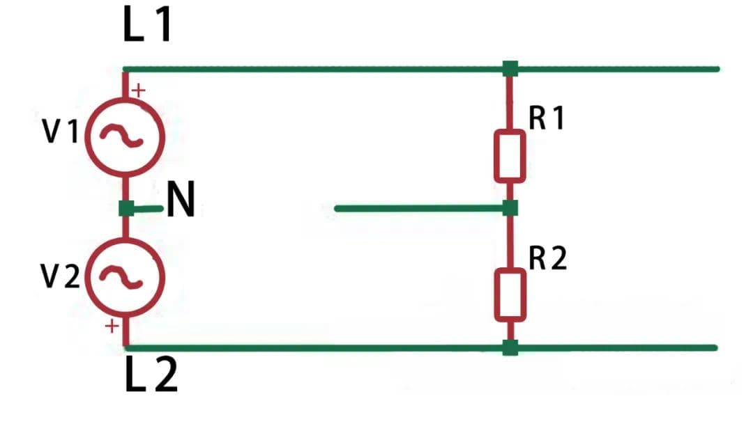
Figure 3 Zero line open circuit diagram
As shown in Figure 3, V1 represents the first phase voltage, V2 represents the second phase voltage, R1 and R2 respectively represent the LED driver power normally installed in the line. When the neutral line (N) on the line is disconnected as shown in the figure, the led power R1 and R2 on the two branches are equivalent to being connected to 380Vac voltage after being connected in series. Due to the difference in input internal resistance, when one of the driving power sources is charged to start, the internal resistance becomes smaller, and most of the voltage may be applied to the other driving power source, causing its overvoltage damage and failure. Therefore, it is recommended that on the same power distribution branch, the switch or circuit breaker should be disconnected together, and the neutral line should not be disconnected only. Do not place the power distribution fuse on the neutral line, and avoid poor contact of the neutral line on the line.
▲ The fluctuation range of the power grid is beyond the reasonable range
When the wiring of the branch circuit of the same transformer grid is too long and there is large-scale power equipment in the branch circuit, the grid voltage will fluctuate violently when the large-scale equipment starts and stops, and even cause the grid to become unstable. When the instantaneous voltage of the power grid exceeds 310Vac, the led driver power supply may be damaged (even if there is a lightning protection device, it will not work, because the lightning protection device is to deal with pulse spikes at the level of tens of uS, and the fluctuation of the power grid may reach tens of mS, or even hundreds of mS). Therefore, special attention should be paid when there are large electric machinery on the power grid of the street lamp lighting branch. It is best to monitor the fluctuation range of the power grid, or to supply power with a separate power grid transformer.
▲ The line trips frequently
Too many lamps connected to the same branch lead to overload on a certain phase and uneven power distribution among the phases, resulting in frequent tripping of the line.
▲ LED Driver power cooling
When the led driving power supply is installed in a non-ventilated environment, the casing of the led driver power supply should be in contact with the led strip casing as much as possible. If conditions permit, apply heat-conducting glue or paste a heat-conducting pad on the contact surface between the casing and the lamp casing to improve the heat dissipation performance of the led power transformer. Ensure the life and reliability of the led driver power supplies.
To sum up, there are many details that need to be paid attention to in the actual application of LED driver power supply. Many problems need to be analyzed and adjusted in advance to avoid unnecessary failure and loss!